M12 Connector Wiring Diagram: All Codings & Color Codes
M12 connector wiring diagrams for every coding: A, B, D and X pinouts with standard wire colors, plus how to wire a field-attachable connector correctly.
M12 Connector Wiring Diagram: All Codings & Color Codes
Quick AnswerOn this page
Quick Answer
There is no single M12 wiring diagram — the correct one depends on the connector's coding and pin count. A-coded connectors follow the familiar brown/white/blue/black/grey sensor color code; B-coded connectors carry PROFIBUS; D- and X-coded connectors carry Ethernet pairs; and power codings use their own conventions. This guide brings the standard wiring diagrams together in one place, so you can find the right pinout, match conductor colors to contacts, and wire any M12 connector correctly.
How to Use a Wiring Diagram
Wiring an M12 connector comes down to three pieces of information: the coding, the pin count, and the gender of the face you are terminating. Together these identify exactly one pinout. Once you have the right diagram, you connect each conductor to its contact either by wire color or by pin number, following the table.
Two cautions apply to every M12 type. First, gender: a male face and a female face are mirror images, so the same pin number sits in a different physical position on each — always use the diagram for the face in your hand. Second, never assume a color or a pin meaning carries across codings: pin 1 is a supply contact on an A-coded connector but part of an Ethernet pair on a D-coded one. With those in mind, the diagrams below cover the common codings.
A-Coded Wiring (Sensors & I/O)
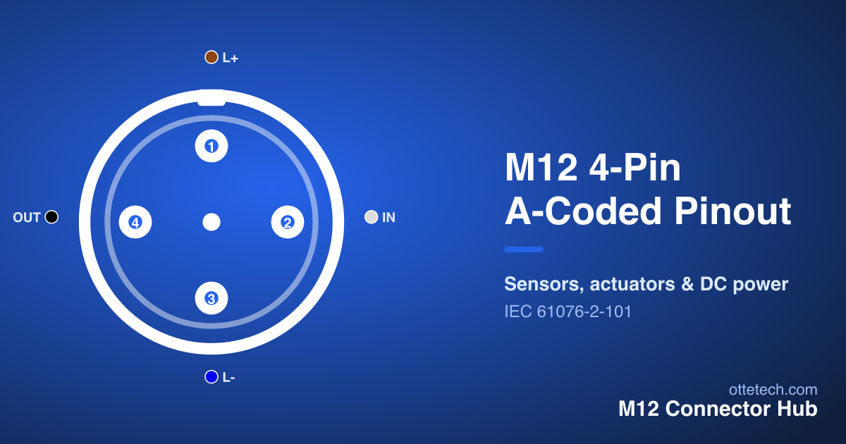
A-coding is the workhorse for sensors, actuators and general I/O. The standard color code makes it fast to wire: pin 1 brown (L+), pin 2 white, pin 3 blue (L-), pin 4 black, and pin 5 grey on 5-pin versions. The brown-and-blue supply pair mirrors common DC conventions.
| Pin | Signal | Wire Color | Function |
|---|---|---|---|
| 1 | L+ | Brown | +24V DC |
| 2 | IN | White | Input Signal |
| 3 | L- | Blue | 0V / Ground |
| 4 | OUT | Black | Signal Output |
The 4-pin layout above is the most common, used for three- and four-wire sensors. The 5-pin version adds a contact for a second signal or a functional earth and shield, while the 8-pin version provides multiple I/O channels. For configuration-specific detail, see the 4-pin pinout, 5-pin pinout and 8-pin pinout guides. Across all of them the colors and supply convention stay consistent, which is a large part of why A-coding is so widely standardised.
B-Coded Wiring (PROFIBUS)
The B-coded connector is the M12 pinout for PROFIBUS fieldbus. Its five contacts carry the data pair, a data ground and a shield, with an optional bus supply — not the sensor signals of the A-coded layout.
| Pin | Signal | Wire Color | Function |
|---|---|---|---|
| 1 | VP | Red | Power Supply +5V |
| 2 | RxD/TxD-P | Green | Data Line + |
| 3 | DGND | Black | Data Ground |
| 4 | RxD/TxD-N | Yellow | Data Line - |
| 5 | Shield | Gray | Cable Shield |
Because B-coding is keyed differently, a B-coded connector cannot be mated with an A-coded 5-pin part, which prevents a fieldbus lead being plugged into a sensor port. When wiring PROFIBUS, keep the data pair together and carry the shield through end to end to maintain signal integrity. For how this fits the wider coding system, see the M12 connector types guide.
D-Coded Wiring (100 Mbit Ethernet)
D-coding is the M12 pinout for 100 Mbit industrial Ethernet — PROFINET and EtherNet/IP. Its four contacts carry the two pairs of 100BASE-TX: one transmit pair and one receive pair. There is no power on a standard D-coded connector; it is a data-only interface.
| Pin | Signal | Wire Color | Function |
|---|---|---|---|
| 1 | TX+ | Yellow | Transmit Data + |
| 2 | RX+ | White | Receive Data + |
| 3 | TX- | Orange | Transmit Data - |
| 4 | RX- | Blue | Receive Data - |
Ethernet codings do not follow the A-coded color sequence — they use pair colors instead, so always read the table for the specific cordset rather than assuming brown is positive supply. Keep each pair twisted right up to the contacts and carry the shield through for a reliable link. For the full picture, see the D-coded for PROFINET guide.
X-Coded Wiring (Gigabit & 10 Gigabit)
When the network needs Gigabit or 10 Gigabit Ethernet, the 8-pin X-coded connector is the pinout. Its eight contacts form four shielded pairs, with internal shielding between the pairs that controls crosstalk at high data rates.
| Pin | Signal | Wire Color | Function |
|---|---|---|---|
| 1 | DA+ | White/Orange | Pair A Data + |
| 2 | DA- | Orange | Pair A Data - |
| 3 | DB+ | White/Green | Pair B Data + |
| 4 | DC+ | White/Blue | Pair C Data + |
| 5 | DC- | Blue | Pair C Data - |
| 6 | DB- | Green | Pair B Data - |
| 7 | DD+ | White/Brown | Pair D Data + |
| 8 | DD- | Brown | Pair D Data - |
As with D-coding, the X-coded connector is data-only and follows pair colors rather than the sensor code. Reaching the rated speed depends on the whole link: the cable must be shielded and category-rated, and the four-pair shield carried end to end. For protocol-specific wiring such as EtherCAT, see the X-coded for 10GbE and M12 for EtherCAT guides.
Wire Color Code Summary
The table below summarises the standard A-coded color code, which covers the great majority of sensor and I/O wiring. Ethernet (D, X) and power codings follow their own conventions, so use this table only for A-coded connectors and read the pinout table for any other coding.
| Pin | Signal (A-coded) | Wire color | |-----|------------------|------------| | 1 | L+ (supply +) | Brown | | 2 | Signal / IN | White | | 3 | L- (supply -) | Blue | | 4 | Signal / OUT | Black | | 5 | FE / shield | Grey |
The brown-and-blue supply pair is the anchor: identify it first and the rest of an A-coded connector follows. Because this code is standardised under IEC 61076-2-101, a cordset from one supplier wires the same way as a device from another, which is what makes field wiring quick and repeatable.
Wiring a Field-Attachable Connector
Field-attachable connectors let you make custom cable lengths on site, at the cost of careful termination. The procedure is the same regardless of coding: strip the cable to the connector's specification, identify the coding and gender, and connect each conductor to its contact by color or number following the pinout table. On screened and Ethernet types, terminate the shield to its designated contact or the connector body as specified, and keep Ethernet pairs twisted to the contact.
Before energising, verify continuity with a meter against the pinout table, contact by contact. This single step catches the most common faults — a transposed pair, an open contact, or a male/female mix-up — before they reach the machine. A few minutes with a meter is far cheaper than fault-finding a sensor that powers up but never switches, or an Ethernet link that negotiates at the wrong speed.
Finding the Right Diagram
To confirm any M12 wiring diagram interactively, use the Pinout Viewer: it covers every coding and pin count in our data, draws the diagram programmatically, lets you switch between male and female views, and highlights a contact across both diagram and table. For the wider background on reading pinouts, see the M12 connector pinout pillar guide. And if you are still selecting a connector rather than wiring one, the connector selector filters by application, protocol, pin count and IP rating. To order a specific part, browse our M12 connectors by pin count: 4-pin, 5-pin, 8-pin and 12-pin.
Key Takeaways
- There is no single M12 wiring diagram — it depends on coding, pin count and gender.
- A-coded color code: pin 1 brown, pin 2 white, pin 3 blue, pin 4 black, pin 5 grey; brown/blue is the supply.
- B-coded carries PROFIBUS; D- and X-coded carry Ethernet pairs and follow pair colors, not the sensor code.
- Always match the diagram to the specific coding and gender; never assume a color or pin meaning across codings.
- Verify continuity with a meter against the pinout table before energising a field-attachable connector.
Frequently asked questions
- Is there a single M12 connector wiring diagram?
- No. The wiring diagram depends on the coding and pin count. An A-coded sensor connector, a B-coded PROFIBUS connector, a D-coded Ethernet connector and an X-coded high-speed connector each have their own pinout and color code. Always match the diagram to the specific coding and pin count.
- What are the standard M12 A-coded wire colors?
- For A-coded connectors the standard color code is pin 1 brown, pin 2 white, pin 3 blue, pin 4 black, and pin 5 grey on 5-pin versions. The brown/blue pair is the supply. Ethernet and power codings use different conventions.
- How do I wire a field-attachable M12 connector?
- Identify the coding and gender, find the matching pinout diagram, then connect each conductor to its contact by color or number per the table. Keep pairs twisted on Ethernet types, carry the shield through, and verify continuity with a meter before energising.
- Are M12 wire colors the same on every connector?
- No. The brown/white/blue/black/grey code is for A-coded signal connectors. D- and X-coded Ethernet connectors follow pair colors, and power codings use their own conventions. Always read the table for the specific connector rather than assuming colors.
Need M12 connectors for your project?
Find the right part with our selector, or send us your requirements for a quote.