M12 4-Pin Connector: Pinout, Wiring & Applications
M12 4-pin connector pinout and wiring: standard A-coded pin assignment, wire colors, 3-wire vs 4-wire sensors, and how D-coded 4-pin differs.
M12 4-Pin Connector: Pinout, Wiring & Applications
Quick AnswerOn this page
Quick Answer
The M12 4-pin connector is the most common M12 configuration, used mainly in A-coding for three- and four-wire sensors and simple actuators. In the standard A-coded pinout, pin 1 is the positive supply (brown), pin 3 is the negative supply (blue), and pins 2 and 4 carry signals (white and black). Note that a 4-pin D-coded Ethernet connector shares the pin count but has a completely different pinout — always specify the coding, not just "4-pin".
The 4-Pin A-Coded Pinout
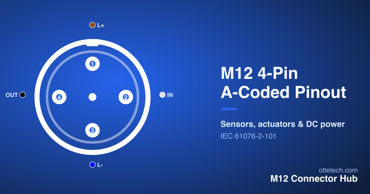
The diagram below shows the standard 4-pin A-coded layout. Hover any contact to highlight it in the table.
| Pin | Signal | Wire Color | Function |
|---|---|---|---|
| 1 | L+ | Brown | +24V DC |
| 2 | IN | White | Input Signal |
| 3 | L- | Blue | 0V / Ground |
| 4 | OUT | Black | Signal Output |
In the usual convention, pin 1 is the positive supply (brown) and pin 3 is the negative supply (blue), forming the power pair, while pins 2 and 4 carry signals — commonly a switching output on pin 4 (black). This is the workhorse layout for sensors across automation. For how to read the diagram, including the male/female mirror image, see the M12 connector pinout guide, and explore other configurations in the Pinout Viewer.
Wire Colors
A-coded M12 connectors follow a standard color code that makes wiring fast and predictable: pin 1 brown, pin 2 white, pin 3 blue, pin 4 black. The brown-and-blue supply pair mirrors common DC power conventions, so power is easy to identify at a glance. These colors apply to A-coded signal connectors; Ethernet and power codings use different conventions, so never assume the brown/blue code on a non-A-coded 4-pin part — always read the table for the specific connector.
When terminating a field-wireable connector, match each conductor color to the pinout table contact by contact, and verify continuity with a meter before energising. Getting a color wrong here is a frequent cause of a sensor that powers up but never switches.
3-Wire vs 4-Wire Sensors
The 4-pin layout flexibly serves both three- and four-wire sensors. A three-wire sensor uses the two supply contacts plus a single switching output, leaving the fourth contact unused or available for a second output — the same job a dedicated 3-pin connector does with the unused contact removed. A four-wire sensor uses all four contacts, typically for two outputs or a combined output and diagnostic signal.
The output type — PNP or NPN — is a property of the sensor, not the connector: the pinout tells you which contact is the output, and the datasheet tells you its electrical type. This is why you should always confirm the device's wiring requirements against its datasheet even when the connector pinout is standard. To choose the right sensor connector for your wiring, the connector selector filters by application and pin count.
A practical tip: when a three-wire sensor leaves one contact unused, do not assume that contact is safe to repurpose for an unrelated signal — keep it unconnected unless the datasheet says otherwise, since some devices reserve it. Sticking to the documented assignment avoids surprises and keeps the wiring consistent across identical sensors on a machine, which makes maintenance and fault-finding far easier.
Male vs Female: Reading the Right Face
A point that trips people up on every M12 pinout, including the 4-pin, is gender. A male connector carries pins and a female carries sockets, and the two are mirror images of each other. The signal on a given pin number is the same on both — pin 1 is electrically pin 1 either way — but its physical position flips between the plug and the socket it mates with. Wiring to the male diagram when you are actually terminating the female end (or the reverse) reverses the contacts and produces a connection that does not work.
So before wiring a 4-pin connector, confirm whether you are looking at the male or female face, and use the diagram for that gender. The same applies to panel versus cable connectors, which you view from opposite sides as you work. The Pinout Viewer lets you flip between male and female views to match whichever end is in your hand, and the M12 connector pinout guide explains the convention in full.
4-Pin Applications
The 4-pin A-coded connector dominates sensor and actuator wiring because it carries everything a typical discrete device needs — supply plus one or two signals — in the smallest practical contact count. Proximity sensors, photoelectric sensors, simple valves and basic I/O points are overwhelmingly 4-pin. Its ubiquity also means cordsets are cheap and stocked everywhere, in straight and angled bodies, so maintenance is quick.
When a device needs an extra signal, a functional earth or a shield, the 5-pin A-coded version is the next step up; for multi-channel devices, the 8-pin layout follows. For the broader range of pin counts and how they map to applications, see the what is an M12 connector and 8-pin pinout guides.
Mounting and Cordset Options
Because the 4-pin A-coded layout is so common, it comes in the widest choice of mechanical formats, all sharing the same pinout. You can choose straight or right-angled bodies to suit the installation, a range of cordset lengths, and either pre-moulded cordsets or field-wireable connectors. Pre-moulded cordsets are sealed at the factory and fastest to fit; field-wireable connectors let you make custom lengths on site at the cost of careful termination.
This flexibility means you can pick the mechanical form that fits the space without relearning the wiring — the contacts are identical across formats. When space around a sensor is tight, an angled body often routes the cable more neatly than a straight one. To compare available parts and formats — including custom cordsets and field-wireable options — browse our 4-pin M12 connectors or filter with the connector selector.
Don't Confuse It With 4-Pin D-Coded
Because "4-pin M12" is ambiguous, it is worth repeating: a 4-pin A-coded sensor connector and a 4-pin D-coded Ethernet connector are different parts. They have different keying, pinout and signals, and they cannot be mated together. If you are wiring Ethernet rather than a sensor, you need the D-coded version — see the D-coded for PROFINET guide. Always specify the coding alongside the pin count to avoid ordering the wrong cordset.
Key Takeaways
- The 4-pin A-coded connector is the most common M12 layout, used for 3- and 4-wire sensors and simple actuators.
- Standard pinout: pin 1 L+ (brown), pin 2 signal (white), pin 3 L- (blue), pin 4 output (black).
- The brown/blue pair is the supply; always confirm the signal contacts against the device datasheet.
- 3-wire sensors use three contacts; 4-wire sensors use all four — the output type (PNP/NPN) is set by the sensor.
- A 4-pin D-coded Ethernet connector is a different part — specify the coding, not just "4-pin".
Frequently asked questions
- What is the M12 4-pin pinout?
- For a 4-pin A-coded M12 connector the common assignment is pin 1 = L+ (brown), pin 2 = signal (white), pin 3 = L- (blue) and pin 4 = signal/output (black). Confirm against the device datasheet, as the exact use of the signal contacts depends on the device.
- What are the wire colors for a 4-pin M12 connector?
- The standard A-coded color code is pin 1 brown, pin 2 white, pin 3 blue, pin 4 black. The brown/blue pair is the supply, mirroring common DC conventions.
- What is the difference between 3-wire and 4-wire sensors on M12?
- A 3-wire sensor uses the supply pair plus one switching output (three contacts), leaving the fourth contact unused or for a second output. A 4-wire sensor uses all four contacts, typically for two outputs or a combined output/diagnostic.
- Is a 4-pin D-coded connector the same as a 4-pin A-coded one?
- No. Both have four contacts, but the D-coded version is keyed for 100 Mbit Ethernet (PROFINET/EtherNet-IP) with a different pinout, while the A-coded version is for sensors and I/O. They cannot be mated together.
Looking for 4-Pin M12 connectors?
Browse our 4-Pin M12 range, or send us your requirements for a quote — including custom assemblies and samples.