M12 5-Pin Connector: Pinout, Wiring & Color Code
M12 5-pin connector pinout: standard A-coded sensor assignment, 5-pin B-coded PROFIBUS pinout, wire colors, and how the fifth contact is used.
M12 5-Pin Connector: Pinout, Wiring & Color Code
Quick AnswerOn this page
Quick Answer
The M12 5-pin connector is the next step up from the 4-pin layout, adding a fifth contact for an extra signal, a second output, an analogue value, or a functional earth and shield. In the standard A-coded pinout, pin 1 is the positive supply (brown), pin 3 is the negative supply (blue), pins 2 and 4 carry signals (white and black), and pin 5 (grey) carries the additional function. A 5-pin B-coded connector shares the contact count but is a completely different PROFIBUS pinout — so always specify the coding alongside "5-pin".
The 5-Pin A-Coded Pinout
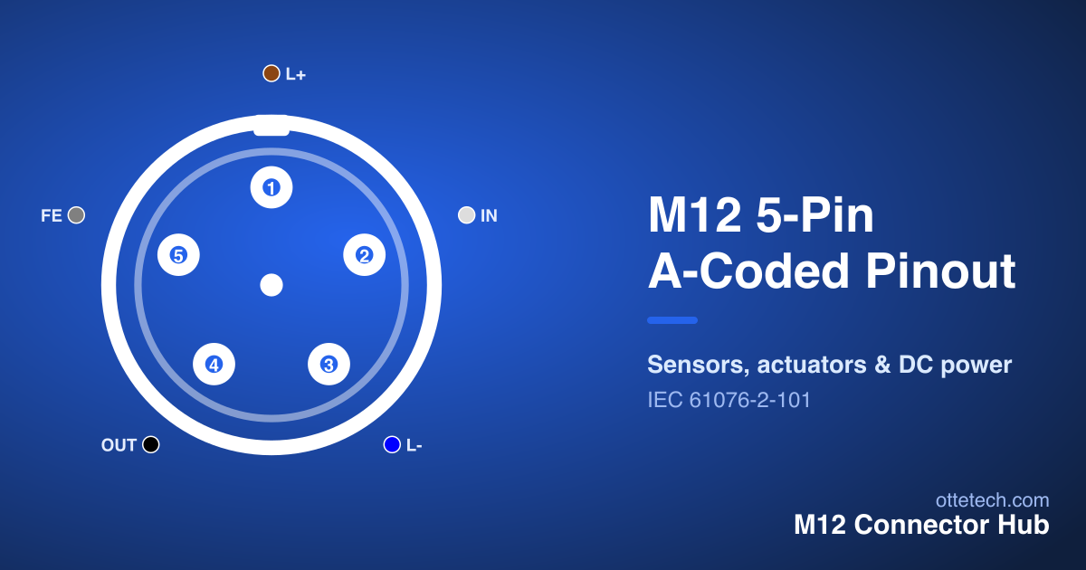
The diagram below shows the standard 5-pin A-coded layout. Hover any contact to highlight it in the table.
| Pin | Signal | Wire Color | Function |
|---|---|---|---|
| 1 | L+ | Brown | +24V DC |
| 2 | IN | White | Input Signal |
| 3 | L- | Blue | 0V / Ground |
| 4 | OUT | Black | Signal Output |
| 5 | FE | Gray | Functional Earth / Shield |
Because the first four contacts mirror the 4-pin A-coded arrangement, anyone already comfortable with the 4-pin pinout can wire a 5-pin A-coded connector with confidence — only the role of pin 5 needs checking against the device. The brown-and-blue supply pair follows the same DC convention, pins 2 and 4 carry signals, and pin 5 (grey) is the new contact. This makes the 5-pin version the standard choice for devices that combine I/O with diagnostics, or that need a dedicated shield or functional-earth connection.
What Pin 5 Does
The defining feature of the 5-pin layout is that fifth contact, and its role is not fixed. On many sensors and actuators pin 5 is a functional earth (FE) or a connection to the cable shield, improving immunity in electrically noisy environments. On others it carries a second switching output, an analogue process value, or an enable/diagnostic line. Because the assignment varies, pin 5 is exactly the contact you must confirm against the datasheet before wiring — the supply and primary signal follow the 4-pin convention, but pin 5 does not have a single universal meaning.
This flexibility is why the 5-pin A-coded connector is so widely used: a single mechanical format covers four-wire sensors that need one extra line, five-wire devices, and screened connections, all on the same familiar layout. When you standardise on 5-pin cordsets across a machine, you gain the spare contact without changing connector type.
Wire Colors
A-coded M12 connectors follow a standard color code that makes wiring fast and predictable: pin 1 brown, pin 2 white, pin 3 blue, pin 4 black, and pin 5 grey. The brown-and-blue supply pair mirrors common DC power conventions, so the supply is easy to identify at a glance, and the grey pin 5 is visually distinct for the shield or functional-earth role it usually plays.
These colors apply to A-coded signal and I/O connectors. Other codings use their own conventions, so never assume the brown/blue/grey sequence on a non-A-coded 5-pin part. When terminating a field-wireable connector, match each conductor color to the pinout table contact by contact and verify continuity with a meter before energising. For the full color code across every coding, see the M12 connector wiring diagram.
The 5-Pin B-Coded Pinout (PROFIBUS)
Not every 5-pin M12 is a sensor connector. The 5-pin B-coded connector is the PROFIBUS fieldbus pinout, with its own keying and a contact assignment that is completely different from the A-coded version.
| Pin | Signal | Wire Color | Function |
|---|---|---|---|
| 1 | VP | Red | Power Supply +5V |
| 2 | RxD/TxD-P | Green | Data Line + |
| 3 | DGND | Black | Data Ground |
| 4 | RxD/TxD-N | Yellow | Data Line - |
| 5 | Shield | Gray | Cable Shield |
Here the contacts carry the PROFIBUS data lines and an optional bus supply rather than sensor signals: the data pair, a data ground and a shield connection make up the working contacts. Because the B-coded connector is keyed differently, it physically cannot be mated with an A-coded 5-pin part — a deliberate safeguard that stops a fieldbus cable being plugged into a sensor port or vice versa. If you are wiring PROFIBUS, this is the pinout you need; for sensors and I/O, use the A-coded version above. For how the codings differ in general, see the M12 connector types guide.
5-Pin A-Coded vs B-Coded at a Glance
| Feature | 5-Pin A-Coded | 5-Pin B-Coded | |---------|---------------|---------------| | Primary use | Sensors, actuators, I/O | PROFIBUS fieldbus | | Pin 1 | L+ supply (brown) | Bus supply VP (optional) | | Working contacts | Supply pair + signals + FE/shield | Data pair + data ground + shield | | Keying | A | B (not cross-matable with A) | | Standard | IEC 61076-2-101 | IEC 61076-2-101 / IEC 61158 |
The table makes the core point clear: the pin count is identical, but the keying, pinout and purpose are not. This is why the coding must always be specified, and why you should read the table for the specific connector rather than relying on contact count alone.
When to Use 5-Pin
The 5-pin A-coded connector is the right choice whenever a four-wire device needs one more line than the 4-pin layout provides — a second output, an analogue signal, or a dedicated functional earth and shield. It is extremely common on photoelectric and proximity sensors with diagnostics, on actuators that report status, and on screened sensor connections in noisy environments.
When even five contacts are not enough — for multi-channel devices or dense I/O — the 8-pin layout is the next step up. If you are still choosing a connector rather than wiring one, the connector selector filters the full range by application, pin count and IP rating, and our 5-pin M12 connectors catalogue lists the available parts. To confirm any configuration interactively, including the male/female mirror view, use the Pinout Viewer.
Male vs Female: Reading the Right Face
As with every M12 pinout, gender matters. A male connector carries pins and a female carries sockets, and the two faces are mirror images. The signal on a given pin number is the same on both — pin 1 is electrically pin 1 either way — but its physical position flips between plug and socket. Wiring to the male diagram while terminating the female end reverses the contacts and produces a connection that does not work, so always confirm which face you are looking at and use the diagram for that gender. The M12 connector pinout pillar explains the convention in full.
Key Takeaways
- The 5-pin A-coded connector adds a fifth contact to the 4-pin layout for an extra signal, second output, or functional earth/shield.
- Standard A-coded pinout: pin 1 L+ (brown), pin 2 signal (white), pin 3 L- (blue), pin 4 output (black), pin 5 FE/shield (grey).
- Pin 5 has no single universal meaning — always confirm its role against the device datasheet.
- The 5-pin B-coded connector is a different part: the PROFIBUS pinout, keyed so it cannot mate with A-coded.
- Always specify the coding, not just "5-pin", to avoid ordering the wrong cordset.
Frequently asked questions
- What is the M12 5-pin pinout?
- For a 5-pin A-coded M12 connector the standard assignment is pin 1 = L+ (brown), pin 2 = signal (white), pin 3 = L- (blue), pin 4 = output (black) and pin 5 = functional earth or shield (grey). The first four contacts mirror the 4-pin A-coded layout, with pin 5 adding the extra function.
- What are the wire colors for a 5-pin M12 connector?
- The standard A-coded color code is pin 1 brown, pin 2 white, pin 3 blue, pin 4 black and pin 5 grey. The brown/blue pair is the supply. These colors apply to A-coded connectors; B-coded PROFIBUS and other codings use different conventions.
- Is a 5-pin A-coded connector the same as a 5-pin B-coded one?
- No. Both have five contacts but they are keyed differently and have different pinouts. The A-coded 5-pin is for sensors and I/O; the B-coded 5-pin is the PROFIBUS fieldbus pinout. They cannot be mated together.
- What is pin 5 used for on an M12 5-pin connector?
- On a 5-pin A-coded connector pin 5 is typically a functional earth or cable shield connection, but it can also carry a second signal or analogue value. Always confirm the role of pin 5 against the device datasheet before wiring it.
Looking for 5-Pin M12 connectors?
Browse our 5-Pin M12 range, or send us your requirements for a quote — including custom assemblies and samples.