M12 3-Pin Connector: Pinout, Wiring & Color Code
M12 3-pin connector pinout: the A-coded 3-wire sensor assignment (pin 1 L+, pin 3 L-, pin 4 output), wire colors, why pin 2 is skipped, and when to use it.
M12 3-Pin Connector: Pinout, Wiring & Color Code
Quick AnswerOn this page
Quick Answer
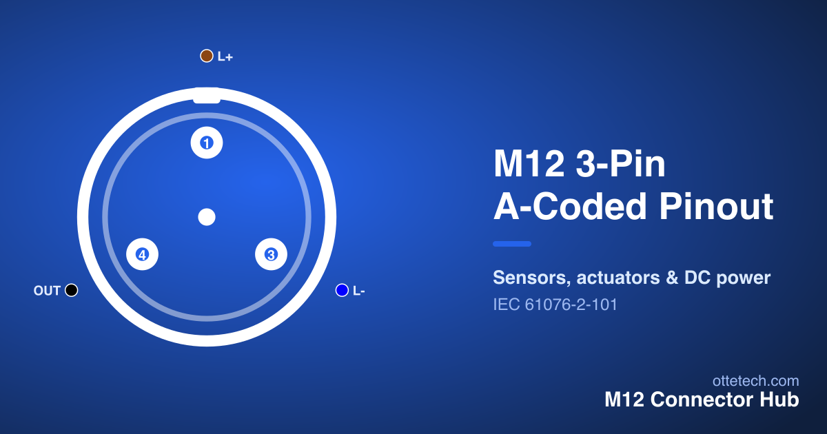
The M12 3-pin connector is the 3-wire DC sensor connector. In the standard A-coded pinout, pin 1 is the positive supply (L+, brown), pin 3 is the negative supply (L-, blue), and pin 4 is the switching output (black) — and pin 2 is not used. The brown/blue pair powers the sensor and the black wire carries its output. The pin numbering deliberately matches the 4-pin A-coded layout, so the same pin numbers always mean the same thing whether a device has three contacts or four.
The 3-Pin A-Coded Pinout
The diagram below shows the standard 3-pin A-coded layout. Hover any contact to highlight it in the table.
| Pin | Signal | Wire Color | Function |
|---|---|---|---|
| 1 | L+ | Brown | +24V DC |
| 3 | L- | Blue | 0V / Ground |
| 4 | OUT | Black | Signal Output |
The three working contacts are the supply pair and a single output: pin 1 (L+) and pin 3 (L-) deliver the DC supply — typically +24 V and 0 V — and pin 4 carries the sensor's switching output. This is exactly the set of connections a 3-wire sensor needs, which is why the 3-pin A-coded connector is the standard choice for that family of devices. It is defined under the same IEC 61076-2-101 A-coding standard as the rest of the A-coded range, so it shares the keying and the numbering convention.
Wire Colors
A-coded M12 connectors follow a standard color code that makes wiring fast and predictable. On the 3-pin connector that means pin 1 brown, pin 3 blue, pin 4 black:
- Brown (pin 1) — L+, the positive supply, usually +24 V DC.
- Blue (pin 3) — L-, the negative supply or 0 V reference.
- Black (pin 4) — the switching output.
The brown-and-blue supply pair mirrors common DC power conventions, so the supply is easy to identify at a glance, and black is consistently the output. These colors apply to A-coded connectors; other codings use their own conventions, so never assume the brown/blue/black sequence on a non-A-coded part. When terminating a field-wireable connector, match each conductor color to the pinout table contact by contact and verify continuity with a meter before energising. For the full color code across every coding, see the M12 connector wiring diagram.
Why Pins 1, 3 and 4 — and Not 1, 2, 3?
The most common question about the 3-pin connector is its numbering: why does it use pins 1, 3 and 4 and skip pin 2? The answer is consistency. The A-coded family numbers its contacts so that a given pin number always carries the same function across pin counts. On a 4-pin A-coded connector, pin 1 is L+, pin 2 is a signal, pin 3 is L-, and pin 4 is the output. A 3-wire sensor needs the supply pair and one output — so it keeps pins 1, 3 and 4 and simply omits pin 2, the second signal.
This is genuinely useful in practice. A 3-wire sensor can be wired to a 4-pin cordset using exactly the same pins 1, 3 and 4, leaving pin 2 unconnected, and it will behave identically. Maintenance staff do not have to relearn the assignment when moving between 3- and 4-pin parts, and a sensor's documentation can refer to "pin 4 output" regardless of whether the connector has three or four contacts.
3-Wire Sensors: PNP vs NPN
The 3-pin connector is defined by the 3-wire sensor it serves. A 3-wire sensor uses two wires for power and one for the output signal, which is what the pin 1 / pin 3 / pin 4 arrangement provides. What the connector does not tell you is the output type: a sensor can be PNP (the output switches to the positive supply) or NPN (the output switches to the negative supply). That is a property of the sensor, not the connector — the pinout tells you which contact is the output, and the datasheet tells you its electrical type. Always confirm PNP versus NPN against the device documentation so the output is wired into the controller input correctly, even though the connector pinout is standard.
When to Use 3-Pin Instead of 4-Pin
The 3-pin connector is the right choice when a device needs only one output alongside its supply — the classic case being a simple proximity or photoelectric sensor with a single switching signal. It is compact and uses the minimum number of contacts for the job.
When a device needs more — a second output, an analogue value, or a diagnostic line — the 4-pin connector adds pin 2 for that second signal, and the 5-pin connector adds a fifth contact for a shield or functional earth. Because the numbering is shared, stepping up is straightforward: the supply and first output stay on the same pins. In practice many installations standardise on 4-pin cordsets even for 3-wire sensors, simply to keep one cable type in stock, wiring the sensor to pins 1, 3 and 4 and leaving pin 2 spare. Either approach is correct; the 3-pin connector just removes the unused contact. If you are choosing a connector rather than wiring one, the connector selector filters the range by application and pin count.
Male vs Female: Reading the Right Face
As with every M12 pinout, gender matters. A male connector carries pins and a female carries sockets, and the two faces are mirror images. The signal on a given pin number is the same on both — pin 1 is electrically pin 1 either way — but its physical position flips between plug and socket. Wiring to the male diagram while terminating the female end reverses the contacts and produces a connection that does not work, so always confirm which face you are looking at and use the diagram for that gender. The M12 connector pinout pillar explains the convention in full, and the Pinout Viewer lets you switch between male and female views interactively.
Wiring a 3-Pin Connector
Terminating a 3-pin connector follows the same disciplined method as any M12 part, made simpler by the low contact count. First confirm the gender of the face you are wiring, since male and female are mirror images. Then match each conductor to its contact by the standard colors — brown to pin 1 (L+), blue to pin 3 (L-), black to pin 4 (output) — and leave the pin 2 position empty. Tighten the coupling nut to the connector's specified torque so the IP seal and the mechanical lock are both made; an under-tightened M12 is neither sealed nor secure against vibration. Finally, verify each contact with a meter against the pinout before energising, and confirm the sensor's output type (PNP or NPN) matches the controller input. The installation guide covers termination and torque in more detail.
Key Takeaways
- The 3-pin A-coded connector is the 3-wire DC sensor connector: pin 1 L+ (brown), pin 3 L- (blue), pin 4 output (black); pin 2 is not used.
- The numbering matches the 4-pin layout, so a 3-wire sensor uses the same pins 1, 3 and 4 on either connector.
- Output type (PNP or NPN) is set by the sensor, not the connector — confirm it against the datasheet.
- Use 3-pin when only one output is needed; step up to 4-pin or 5-pin for more signals.
- Wire colors are standard A-coded: brown supply +, blue supply −, black output.
Frequently asked questions
- What is the M12 3-pin pinout?
- For a 3-pin A-coded M12 connector the standard assignment is pin 1 = L+ (brown, +24 V DC), pin 3 = L- (blue, 0 V) and pin 4 = output (black). Pin 2 is not used. This is the classic 3-wire DC sensor wiring.
- Why does a 3-pin M12 connector use pins 1, 3 and 4 instead of 1, 2, 3?
- The numbering is kept consistent with the 4-pin A-coded layout so a given pin number always carries the same function. A 3-wire sensor uses the supply pair (pins 1 and 3) plus one output (pin 4), and simply omits pin 2, which is the second signal on a 4-pin connector.
- What are the wire colors for a 3-pin M12 connector?
- The standard A-coded colors are pin 1 brown (L+), pin 3 blue (L-) and pin 4 black (output). The brown/blue pair is the supply, matching common DC conventions; black is the switching output.
- What is a 3-pin M12 connector used for?
- It is the connector for 3-wire DC sensors — proximity and photoelectric sensors that need a supply pair plus a single switching output (PNP or NPN). It is a compact alternative to the 4-pin connector when only one output is required.
- What is the difference between a 3-pin and a 4-pin M12 connector?
- A 3-pin connector carries the supply pair plus one output (pins 1, 3, 4). A 4-pin connector adds pin 2 for a second signal or output. Because the numbering aligns, a 3-wire sensor wired to a 4-pin connector uses the same pins 1, 3 and 4 and leaves pin 2 unconnected.
Need M12 connectors for your project?
Find the right part with our selector, or send us your requirements for a quote.